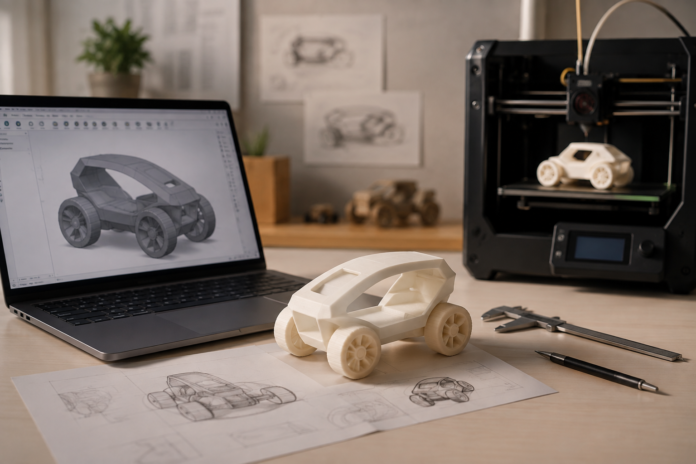

A practical path from design brief and 3D model to export, slicer preview, test print, measured revision, and a portfolio that explains what changed.
Moving from CAD to a 3D print requires more than pressing Export. A beginner needs to define what the object must do, model with dimensions, inspect it from every view, prepare a valid file, use the slicer preview to question orientation and support, print the smallest useful prototype, and revise from physical evidence.
This workflow turns digital art into design practice. The screen is not the enemy, and the first print is not a trophy. CAD is where a young creator makes spatial promises; the prototype reveals whether those promises survive gravity, material, assembly, and another person’s hands.
1. Start with a brief that can be tested
“Make a cool vehicle” produces many possible images but no clear decision. A useful brief identifies a user, an action, and a constraint: “Design a palm-sized vehicle whose front module can be removed without tools and whose wheels turn freely.”
Before modeling, write:
- Who will handle the object?
- What must it do?
- What real object or space controls its size?
- Which feature carries the visual idea?
- What will version one test?
The first prototype should not test everything. Choose one primary question—scale, fit, motion, balance, or handling—and let the rest remain intentionally simple.
2. Establish three controlling dimensions
Begin with the overall envelope, the most important functional opening or connection, and the smallest detail that must remain readable. Measure a real reference such as a hand, shelf, pencil, game board, or existing part.
“Make it bigger” is a visual reaction. “Increase the base so the object remains upright when the module is attached” is a design hypothesis. Dimensions become useful when they connect a number to an expected physical behavior.
Do not dimension every decorative curve at the start. Too many numbers can make a beginner defend early choices. Fix the dimensions that control use, then allow the composition to develop around them.
3. Build a clean model from simple operations
Beginners do not need hundreds of commands. Combining solids, subtracting openings, aligning parts, mirroring a feature, and repeating a module can support sophisticated work. A strong model is understandable enough that the creator can explain how it is built and change one feature without breaking unrelated geometry.
Keep the model organized:
- Name major parts by function rather than leaving a list of anonymous shapes.
- Separate pieces that must move or be printed independently.
- Avoid accidental internal geometry and surfaces that only appear to touch.
- Keep decorative detail subordinate to the prototype question.
- Save a new version before any major structural change.
Guided tools can reduce navigation burden, but the learner must still make visible decisions. a guided 3D printing platform offers one child-centered maker ecosystem; whatever software is used, require the designer to explain at least one decision about proportion, one about function, and one about expression.
4. Inspect the model from five views
Rotation is not a presentation effect. It is an inspection method. Check:
- Front: does the silhouette communicate the idea?
- Side: is the depth plausible, and does the object lean?
- Top: are parts aligned and spaced around the center?
- Underside: what actually touches the build surface or another part?
- Perspective: does the form remain coherent at a normal viewing angle?
Ask the learner to find one potential problem in each view before adding more detail. A front view may hide a hollow back, a joint that never meets, or a top-heavy profile. Maintaining one coherent object across several representations is a core CAD skill.
5. Check whether the file represents a printable object
Before export, confirm that the intended parts are closed solids rather than loose surfaces, that separate moving pieces are actually separate, and that no tiny accidental fragments remain. Use the software’s available inspection or repair tools rather than assuming a clean render equals a clean printable file.
Export in a format supported by the intended workflow and preserve the editable CAD version separately. An exported mesh is a production handoff, not the master design. If the slicer reports unexpected scale, missing surfaces, or separate fragments, return to the CAD file and correct the source instead of patching an unclear problem downstream.
This step differentiates CAD literacy from file conversion. The young designer learns that every stage has a responsibility: the CAD model defines geometry, the export represents it, and the slicer prepares a manufacturing plan.
6. Read the slicer preview as a prediction
| Workflow stage | Main question | Useful evidence | Return to the previous stage when… |
| Design brief | What must the object do for whom? | One user, action, constraint, and test | Success cannot be described |
| CAD model | Is the geometry understandable and editable? | Named parts and controlling dimensions | Parts only appear to touch or the model breaks during edits |
| Export | Did the handoff preserve the intended object? | Correct scale, closed parts, and no accidental fragments | Surfaces disappear or separate pieces merge unexpectedly |
| Slicer preview | How will the object be manufactured? | Orientation, support, travel, walls, and layer preview | Scale or geometry differs from the brief |
| Prototype | What physical behavior answers the question? | Fit, balance, motion, handling, or user observation | The test changes several variables at once |
| Revision | Which single change responds to evidence? | A before-and-after comparison using the same criterion | A new defect replaces the original problem |
The slicer preview shows how the object will be built layer by layer. Before starting a print, inspect:
- Whether the scale matches the brief.
- Which surface meets the build area.
- Where long unsupported features or bridges may appear.
- Whether supports are proposed and where they contact the object.
- How frequently the nozzle travels between isolated areas.
- Whether walls, openings, and small features remain present in the preview.
Orientation is a design decision. Turning a part may improve one surface while weakening another, increase support, change layer direction, or alter cleanup. Ask the learner to compare two orientations and name the tradeoff rather than searching for a universally “correct” pose.
7. Print the smallest prototype that answers the question
A polished full-size first print is expensive evidence. A low-detail prototype invites inspection and shortens the distance between idea and revision.
If fit is uncertain, print a connector strip. If balance is uncertain, print the base and a simplified mass. If handling is the question, print a low-detail shell at the intended scale. If a surface detail may disappear, place several versions on a small sample.
Keep material, profile, orientation, and surrounding geometry consistent when comparing variants. Label every test. The prototype should answer one sentence written before printing: “This version will show whether the module can be removed by hand without wobbling during use.”
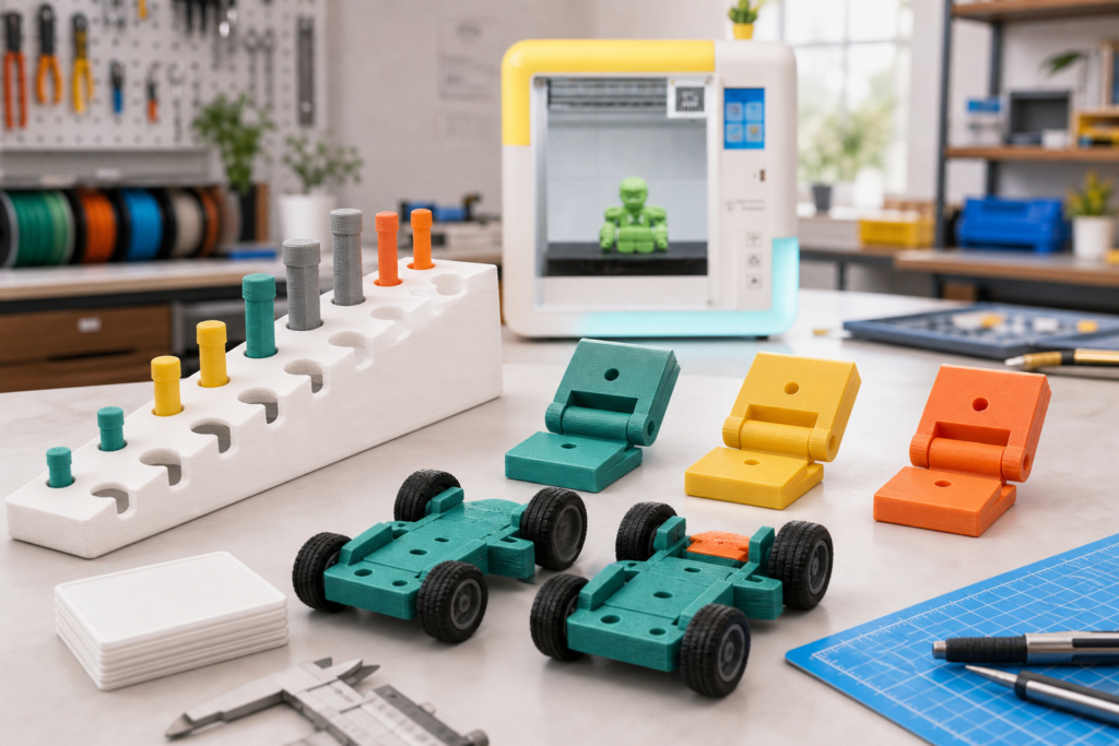
Prototype-study illustration — clearance samples, joint tests, and two versions show how CAD dimensions become physical evidence. No printer product or universal tolerance value is depicted.
8. Treat fit as a local experiment
Two parts can look perfectly aligned on screen and still bind, wobble, or refuse to assemble after printing. Physical fit depends on the intended motion, geometry, material, orientation, profile, and the behavior of the specific setup.
Create a compact strip with several versions of the same peg, hole, slot, hinge, or snap feature. Keep everything except the selected clearance relationship constant. Test by hand and describe behavior rather than hunting for one universal number:
- Too tight to assemble without excessive force.
- Firm and usable for a removable connection.
- Free enough for the intended movement.
- Too loose to hold alignment or load.
Record the selected version and apply that direction to the complete model once. The strip becomes a project-specific calibration artifact. More importantly, it teaches that a dimension is a hypothesis about matter—not a guarantee supplied by the screen.
9. Evaluate behavior, not just appearance
Put the prototype into another person’s hands before explaining it. Observe what the user does: which part they grip, whether they discover the intended motion, where assembly stops, and which feature they misread.
Write observations as behavior rather than praise. “The user held the narrow arm instead of the base” is actionable. “It looks good” is not. The next CAD session should begin with one observed behavior and one chosen change.
Adults and peers should separate evidence from taste. “The connector separated when I lifted the object” identifies a requirement. “I would make the curve more elegant” replaces the creator’s visual judgment with somebody else’s preference.
10. Preserve a compact version history
A final render shows visual ability. A sequence of brief, CAD view, slicer prediction, test part, annotated photo, revised dimension, and final prototype shows design thinking.
Keep only enough evidence to explain the change:
- State the intention in one sentence.
- Show the first version and the physical behavior that challenged it.
- Identify the exact dimension, shape, orientation, or connection changed.
- Compare the next test using the same criterion.
- Explain one tradeoff that remains.
This is a stronger beginner portfolio than a folder of unexplained final files. It makes the creator’s reasoning visible and gives future projects a reference.
Match the system to sustained prototype work
For older children, teens, and learning spaces, enclosed 3D printer for older kids and teens is positioned as a more project-oriented option within an enclosed, guided ecosystem. Compare any system by the complete path from idea to next version: Does the build area fit the intended objects? Can the learner understand what changed? Are material and operating responsibilities clear? Is there an understandable help path after an imperfect print?
Adults should manage placement, setup, compatibility, file review, supervision, maintenance, and all contact with heated or moving components. Young designers can own the brief, composition, measurements, prototype question, observed result, and revision. That division supports independence without confusing creative authority with equipment responsibility.
The prototype completes the CAD lesson
The value of beginner CAD is not that every digital object should become plastic. It is that selected ideas can be tested against dimension, gravity, touch, assembly, and another person’s use.
When a young designer can point to a loose gray connector, show the change in the CAD file, and explain why the revised part now moves correctly, the portfolio contains more than an attractive object. It contains a visible argument: this was the intention, this is what the physical test revealed, and this is how the design responded.
Frequently asked questions
What file format should a beginner use for 3D printing?
Use a format supported by the chosen printer and slicer workflow, and keep the editable CAD source separately. The exported file is a production handoff, not the master design. Confirm scale, separated parts, and visible geometry after import rather than assuming every export behaves identically.
Is a slicer the same as CAD software?
No. CAD software defines and edits the object’s geometry. The slicer converts that geometry into a manufacturing plan and lets the user inspect orientation, supports, travel, walls, and layers. A geometry problem should normally be corrected in the CAD source.
Does every CAD model need supports?
No. Support depends on geometry, orientation, material, profile, and the intended surface quality. Compare orientations in the supported slicer preview and consider the tradeoffs. Do not add supports automatically without checking where they touch the object and how they affect cleanup.
Why can two parts fit on screen but not after printing?
Nominally matching surfaces leave no room for manufacturing variation or movement. Physical fit also depends on material, orientation, geometry, profile, and the intended connection. Use a small labeled fit test rather than relying on a universal clearance value.
What belongs in a beginner CAD portfolio?
Keep the brief, one useful CAD view, the slicer prediction, the first test, the observed behavior, the exact change, and the revised result. This compact sequence shows reasoning more clearly than a folder containing only polished renders and final files.