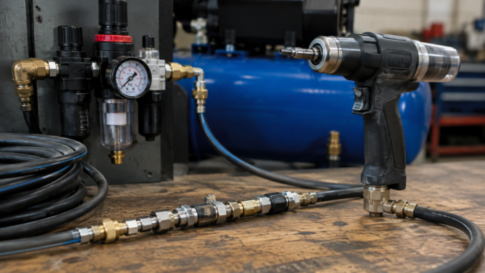

A tool rated for 90 psi is fed from a compressor set to 100 psi and underperforms anyway. Setting force falls short, cycle times stretch, and the operator compensates by holding the trigger longer or running a second cycle.
A gauge at the compressor reads 100. A gauge at the tool inlet, taken while the tool is actuating, reads considerably less. The difference was consumed between those two points, distributed across every fitting, coupling, hose length, and bend in the line.
That loss is measurable and predictable, and it explains most cases of a properly specified tool that does not deliver its rated output.
Static Pressure Is Not Working Pressure
A gauge on an idle system shows static pressure, which is the same throughout the line because nothing is flowing.
The moment a tool actuates, air flows, and flow through any restriction produces a pressure drop. Every component in the path contributes: hose walls, each fitting, each coupling, each bend, and each change in diameter.
The relevant figure is dynamic pressure at the tool inlet during actuation. It is always lower than static pressure, and how much lower depends on the path.
Measuring static pressure and assuming the tool receives it is the source of most misdiagnosis, since the reading looks correct while the tool is starved.
Restriction Concentrates at the Connections
Hose contributes loss along its length, but the sharper losses occur at connection points.
A quick-disconnect coupling forces air through an internal passage substantially smaller than the hose bore. Each coupling in the line imposes a discrete drop, and lines assembled with multiple couplings, adapters, and swivels accumulate them.
Fitting geometry matters as much as size. A fitting with an abrupt internal shoulder or a right-angle turn creates turbulence and greater loss than one with a smooth transition of the same nominal bore.
Undersized fittings on adequately sized hose are common, since the hose is chosen deliberately and the fittings are whatever was on the shelf. The narrowest point in the path governs flow regardless of how generous the rest is.
Selection of Pneumatic Air Connections with full flow paths matched to hose bore removes the largest controllable share of the loss.
Hose Diameter and Length Interact
Loss along a hose rises with length and falls sharply with increased diameter.
Doubling hose length roughly doubles the loss for a given flow. Increasing the internal diameter one step reduces loss substantially, because flow area rises with the square of the diameter.
Long runs of small-bore hose are the worst combination and the most frequent one, since small hose is lighter to handle and long runs are convenient for reach.
Where reach is required, the practical approach is a larger-bore main run to a point near the work, with a short small-bore whip hose at the tool for flexibility. The short flexible section imposes little loss because it is short.
Coiled hose deserves specific mention. Coils are convenient but the coiled geometry adds effective length and continuous curvature, both of which increase loss compared with straight hose of the same nominal length.
Flow Demand Is Intermittent and Peaky
Rivet nut installation tools draw air in short bursts rather than continuously.
The system has to supply the peak demand of that burst, not the average consumption. A compressor sized on average CFM may be adequate on paper and inadequate at the moment of actuation.
Line volume near the tool acts as a local reservoir, buffering the burst. A short length of larger-bore hose close to the tool provides some of this effect, and in-line receivers exist for the purpose on demanding applications.
Multiple tools on a shared line compound the problem when their bursts coincide. A line adequate for one tool may sag noticeably when two operators actuate simultaneously.
Regulators and Filtration Add Their Own Drop
Filter, regulator, and lubricator units in the line each impose restriction.
Regulators have a flow capacity, and drawing beyond it causes downstream pressure to fall below the setpoint during flow. A regulator sized for the tool’s average draw will droop under peak demand.
Filters restrict progressively as elements load with particulate and moisture. A filter that was adequate when installed becomes a significant restriction as it fills, and the degradation is gradual enough to go unnoticed.
Pressure differential across a filter is the direct measure of its condition. Where gauges permit, monitoring it identifies a loading element before it affects tool output.
Leaks Reduce Available Pressure Continuously
Leakage in a compressed air system is common and cumulative.
Leaks at fittings, couplings, and hose fatigue points draw flow continuously, which means the compressor is supplying leakage alongside tool demand. The effect is reduced available pressure and increased compressor run time.
Coupling seals wear from repeated connection cycles. Hose develops porosity and cracking at flex points and near fittings.
Audible leaks are the large ones. Smaller leaks are found by soap solution or ultrasonic detection, and the aggregate from many small leaks frequently exceeds any single audible one.
Diagnosing a Performance Complaint
The sequence isolates where the pressure is going.
Measure static pressure at the compressor and at the tool inlet. They should be close; a large difference indicates leakage or a severe restriction.
Measure pressure at the tool inlet during actuation. This is the working figure and the one to compare against the tool’s requirement.
Where working pressure falls short, work backward: check filter differential, regulator capacity, coupling count and bore, hose diameter and length, and whether other tools share the line.
Each finding has a defined correction, and the largest gains usually come from the connections rather than from a larger compressor.
What Specification Should Cover
Building a line that delivers rated pressure requires specifying the whole path.
Tool requirement in psi and peak CFM. Hose bore sized for the run length rather than for convenience. Fittings and couplings with flow paths matched to hose bore. Regulator capacity above peak demand. Minimum coupling count between source and tool.
Compressor output is the figure most often examined and the one least often at fault.