
Yes — and the bikes most worth converting usually have them. A decent hybrid or hardtail from the last ten years will have hydraulic discs, and the last thing you want to do is throw those away for the cable levers that come in many kit boxes. The good news is that you do not have to. The less good news is that “hydraulic compatible” covers two separate problems, and most installation failures come from solving one and forgetting the other.
This guide separates the two, explains the two ways of getting a cut-off signal from a hydraulic lever, works through the rotor and caliper checks that a wider motor hub forces on you, and gives an installation order that puts the battery on last for a reason.
The Two-Circuit Rule
A converted bike has two braking circuits that share a lever and nothing else.
| Circuit | What it does | What the conversion changes |
| Hydraulic (mechanical) | Lever pressure moves fluid, the caliper clamps the rotor, the bike slows | Nothing, as long as rotor and caliper clear the new hub |
| Electrical (signal) | A sensor tells the controller the lever has moved; the controller stops motor assistance | Everything: this circuit does not exist until you add it |
The hydraulic circuit is yours already and it is excellent. Keep it. The electrical circuit is new, it costs a few pounds, and it is the difference between a motor that stops when you brake and a motor that fights your brakes. Every decision below follows from keeping those two circuits separate in your head.
Getting the signal: two options, one of them wrong for you
Option 1 — replacement e-brake levers. A lever with a built-in switch. Simple, reliable, and only usable with cable brakes, because a cable lever cannot push hydraulic fluid. If your kit arrives with these and you have hydraulic brakes, set them aside.
Option 2 — add-on hydraulic brake sensors. A small sensor attached to your existing lever body, with a magnet on the blade. When the blade moves, the magnet moves away, and the sensor signals the controller. Your brakes stay exactly as they were. KirbEbike kits supply brake sensors or cut-offs with the hydraulic solution chosen by variant; check the product page selector so the right option is in the box.
Add-on sensors are not universal, and anyone who says otherwise has not fitted many. Lever blade shape, the flat area available for the sensor, adhesive preparation, magnet gap and cable exit all decide whether the sensor triggers cleanly. A magnet set too far away never triggers; one that shifts under vibration holds the cut-off on permanently and the bike “loses power” for no obvious reason.
]
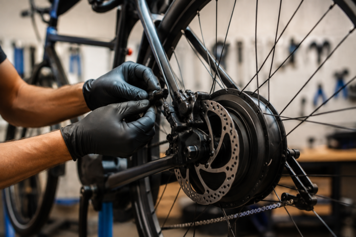
Mountain bike with hydraulic disc brakes converted with a KirbEbike drive system in a workshop
The rotor and caliper checks a wider hub forces on you
A hub motor is wider than the hub it replaces. That moves the rotor mounting face, and a rotor that sits a millimetre off centre drags, squeals or fails to clear the caliper body. Do these six checks before the wheel goes in for good.
- Rotor interface. Six-bolt or Centerlock? The motor wheel must match, and adapters have limits.
- Rotor diameter and thickness. Record them before removing the original wheel. A worn rotor on a heavier, faster bike is a rotor to replace.
- Caliper clearance to the motor shell. Hub motor casings are large. Check the caliper body and the spokes clear it through a full rotation.
- Rotor centring after full axle seating. Push the axle fully home, tighten, spin, and watch the rotor in the caliper slot. Spacers and washers move the disc laterally.
- Approved adapters only. If you want a larger rotor for the extra mass and speed, use an adapter rated for the fork or frame and the rotor size. Larger is not automatically compatible.
- Spin and brake before power. Apply the brake with the wheel spinning and the battery disconnected. A rub you can hear now is a rub you will not hear over the motor.
On a 52V 2000W conversion system the motor wheel can be supplied in several diameters and drivetrain configurations, and none of that removes the need to check rotor alignment on the exact donor frame. Two identical kits on two different frames can need different spacer stacks.
A safe installation order
The order matters more than the tools. Power goes on last because every other step is easier and safer without it.
- Photograph both levers, both calipers, rotor markings and the hose routing.
- Confirm the motor wheel’s rotor standard and your drivetrain interface before ordering.
- Fit the wheel and the axle-retention hardware with the battery disconnected.
- Align rotor and caliper; confirm free rotation and firm braking at the lever.
- Fit the hydraulic cut-off sensors and magnets to clean, flat, degreased surfaces.
- Route the sensor cables with full steering lock and, on suspension bikes, full travel available.
- Connect the controller and test each brake cut-off with the driven wheel off the ground.
- Low-speed braking test away from traffic before normal riding.
Torque arms belong at step 3. On a hydraulic-braked bike with alloy dropouts and anything over 1000W, they are not optional, and fitting them after the rotor is aligned means realigning the rotor.
How to test the electrical cut-off
Wheel off the ground, system on, lowest assist level. Request a little power and pull one lever. The motor should stop within a fraction of a second. Release and confirm assistance returns only when you ask for it again. Repeat for the other lever. Then repeat both tests with the handlebar at full lock each way, because a cable that is fine straight ahead can pull a plug at the steering stop.
If the motor does not stop: disconnect the battery, check the magnet gap, the sensor orientation, the plug seating and the controller’s brake input assignment. Do not “fix” it by moving the magnet into a position that interferes with normal lever travel.
The mistakes that fill the forums
- Assuming a matching plug proves a matching pinout.
- Sticking a sensor to an oily, curved lever surface and wondering why it fell off in the rain.
- Routing the sensor cable so the steering pulls the connector apart.
- Fitting a larger rotor without checking the fork’s maximum rotor size.
- Solving rotor alignment with axle spacers and leaving too little thread for the nut.
- Powering the motor before the rotor is centred and the axle is fully seated.
Every one of these is cheaper to avoid than to fix, and the last one can bend a rotor on the first pull-away.
Braking capacity after conversion
A converted bike is heavier and usually faster, and both increase the energy the brakes must dissipate — speed more than weight, because kinetic energy rises with the square of velocity. Pads, rotor condition, fluid age and the rider’s ability to modulate both brakes matter more than the presence of a sensor. The KirbEbike conversion kit range runs from 250W commuter systems to 4000W off-road builds, so there is no single rotor size that suits every conversion; the donor frame, final mass and the descents you ride decide.
A sensible rule: any kit above 1000W gets fresh pads and a fluid check at installation, and a rotor upgrade if the fork permits one.
Rotor and pad guidance by kit class
There is no single rotor size for “an ebike conversion”, but there is a sensible starting point for each power class once you know the finished weight and where the bike will be ridden.
| Kit class | Typical finished bike weight | Rotor starting point | Pads | Notes |
| 250W front hub (commuter) | 16–19 kg | Keep existing 160 mm | Fresh organic or semi-metallic | Front hub adds little braking demand; check rotor clearance on the motor shell |
| 500W–1000W rear hub | 22–26 kg | 160 mm rear, 180 mm front if the fork allows | Semi-metallic | Heavier and faster; budget for pads at installation |
| 2000W–3000W rear hub | 25–29 kg | 180 mm both ends where frame and fork permit | Sintered or semi-metallic | Long descents heat rotors; larger discs manage temperature, not just force |
| 4000W specialist build | 28 kg + | 203 mm where supported; assess the whole brake system | Sintered | Treat braking as a design task, not an upgrade |
Two cautions. A larger rotor needs an adapter rated for the caliper mount and the fork’s stated maximum; many lightweight forks are limited to 160 or 180 mm. And pad compound changes lever feel: sintered pads bite harder when hot and need a few rides to bed in, so test them on a quiet road before trusting them on a descent.
]
Smart ebike controller with its full wiring harness, including the brake cut-off and display connectors
Frequently asked questions
Do hydraulic brakes work with an ebike conversion kit?
Yes. Keep the hydraulic brakes, confirm the motor wheel’s rotor interface and caliper clearance, and add a hydraulic cut-off sensor to each lever instead of fitting cable e-brake levers.
Are brake cut-off sensors legally required?
Requirements vary by jurisdiction and system. Whatever the legal minimum, a reliable cut-off is an essential safety layer on any throttle- or pedal-assist-controlled conversion.
Can I fit a larger rotor after conversion?
Only if the fork or frame, caliper adapter and hub interface support the larger size. Check the fork’s maximum rotor specification before buying.
Why does the motor stay disabled after I release the brake?
The sensor magnet is probably too close, the lever is not returning fully, or the plug is in the wrong brake input. Disconnect power and correct the installation before riding.
Will a hub motor wheel fit my disc brake?
If the rotor interface matches and the caliper clears the motor shell. Record your rotor standard and diameter before ordering, and expect to adjust spacers on installation.